
Different methods of reducing earth resistance

The earthing resistance of the grounding electrode
2 the contact resistance between the electrode and the surrounding ground it is driven in , so to reduce this resistance to a negligible value ,the electrode should be free of grease and paint and the soil surrounding the electrode shall be packed firmely .
NEC grounding electrodes Requirements
According to the NEC, the ground electrodes consisting of plates, pipe and rods shall conform to the following:
Pipe electrodes : Electrodes of pipe or conduit shall not be smaller than (3/4 in) and requires corrosion protection where made of iron or steel
steel or iron plate electrodes shall be at least 6.4 mm (¼ in) in thickness , but nonferrous plate electrodes shall be at least 1.5 mm (0.06 in.) in thickness.
Rod electrodes : Iron or steel rods must not be smaller than 15.87 mm (5/8 in) in diameter and shall be galvanized for corrosion protection.
Rods electrodes shall fulfill the following requirements :
1) shall not be less than 1.5 m (5 ft) in length.
2) shall be driven, where practicable, below permanent moisure level.
3) shall be separated at least 1.8 m (6 ft) from any other electrode electrodes including those used for signal circuits, lightning system, or any other purpose.

5) If rock bottom is encountered before the earth rod is 8 ft (2.44 m) into the earth, in this case it should be driven into the ground at an angle not over 45° from the vertical to have at least 8 ft (2.44 m) of its length in the ground.
6) if rock bottom is so shallow that it is not possible to get 8 ft (2.44 m) of the rod in the earth at a 45° angle, then it is necessary to lay the rod horizentaly in a 2½ ft (750 mm) deep trench.

How to reduce earth resistance ?
If the earth resistance is high, it can be decreased by one of the following methods:
1) increasing the diameter of the earth rod2) increasing the length of the earth rod
3) Using multiple rods in parallel
4) Chemical treatment of the soil
increasing the diameter of the earth rod
Doubling the diameter of the earth rod will result in reduction in the earth resistance by approximately 10%
increasing the length of the earth rod
Doubling the length of the earth rod will reduce the earth resistance by around 40%

Using multiple rods in parallel
The NEC requires that a single electrode with a resistance to ground greater than 25 Ω should be augmented by an additional electrode.
- If two well-spaced earth rods (of the same size and depth) are driven into the ground,this will result in reduction in the overall earth resistance by about 40%
- If three rods are used,the reduction in the earth resistance will be 60%
- If four rods are used,the reduction will be 66%
The following curve shows this effect :

Each two earth rods should be separated from each other by a distance not less than the depth to which they are driven or preferably twice the depth and the NEC requires that the minimum spacing between two parallel rods driven into the ground is 6 ft .

Measurement of Soil resistivity (Wenner method)
")
Procedures
1) A four terminal instrument like megger earth tester is used to measure the earth resistivity
3) Use a separate four lead wires to connect the four electrodes to the four terminals on the instrument as follows:-
- The two outer electrodes (1 & 4) are connected to the two terminals labelled C1 and C2 (current terminals) on instrument
- The two inner electrodes (2 & 3) are connected to the two terminals labelled P1 and P2 (potential terminals) on instrument
V1 and V2 is referred to a very distant point.
Using ohm's law (R=V/I), the earth tester automatically calculates the earth resistance and its value will appear on the screen of tester.
")

If the soil resistivity measured by the megger earth tester is 20 Ω and the distance between electrodes is 3 m . Calculate the soil resistivity ??
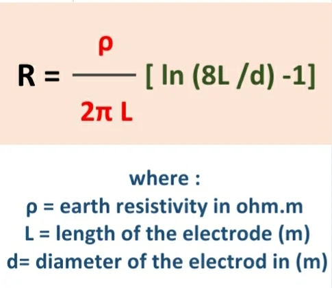
The earthing resistance can be calculated using the following equation :
The following equation can be used to calculate the overall earth resistance for multiple rods:


Calculate the earthing resistance of an earthing electrode of length 3m and its diameter is 16 mm driven in a soil of 50 Ω.m resistivity.
Hence the equivalent earthing resistance will be :
Chemical treatment of the soil
Chemical treatment of the soil is a good way to reduce the earthing resistance of the grounding electrode in situations when we can not drive the electrode into a deeper depths because of hard underlying rock and when using multiple rods is not practical.
1 Soil treatment using chemical compounds
Magnesium sulfate is the most widely used chemical compound because of its low cost and and it has high electrical conductivity and the least corrosive effect .
Installation of chemical compounds
2) Supply a little water into the hole for good absorption of salts (chemicals) periodically.

One of the good advantages of chemical treatment is that it reduces the seasonable variation on resistance that results from wetting and drying out of the soil.
2 Soil treatment using Bentonite material
Bentonite is an off-white sodium montmorillonite clay formed from altered volcanic ash.
It is a moisure retaining clay that is used for reducing the contact earth resistance and increase the effective size of grounding electrodes as a backfill for grounding rods installed in buried holes or as a layer encapsulating earth conductors buried horizentaly in trench.

Advantages of Bentonite as a backfill material
1 Bentonite is a super absorbant material as when it comes into contact with water, it will absorp up to five times its weight and expand up to thirteen times its original dry volume so it increases the serface area contact between the grounding electrode and the surrounding soil which improves the total earthing resistance.2 Bentonite is strongly hydrated in water so it has a great water absorption capability
3 Bentonite has the ability to absorb moisure from the surrounding Soil and to retain water or its moisure content for a considerable period of time at atmospheric pressure, and this will reduce the earth resistance.
4 Bentonite is a non-corrosive material even for a long period of time so it protects the grounding electrode.
5 Bentonite is a stable material because it does not change its characteristics as the time elapses.
6 Bentonite is cost-effective as we can get the required earth resistance by using a little amount of it when compared with other cement based solutions.7 The resistivity of Bentonite depends on its moisure content as its resistivity varies from 3 ohm.m in wet condition and upwards to 18 ohm.m in dry condition .
8 Bentonite can be in the form of granular or powder, the granular form is preferred to be used for filling trenches while powder form is preferred for pouring into boreholes.9 As there is a moisure in the soil, bentonite will retain enclosing the buried earthing rod or electrode and will not get washed away.hence we will not need to replace the bentonite
10 Bentonite shouldn't be used in very dry locations and free draining locations.Bentonite installation
Mixing bentonite
As a rule of thumb assume an expansion ratio of 2:1
1×25 kg bag = 1 ft³ or 0.0283 m³ (dry)
1×25 kg bag = 2 ft³ or 0.0566 m³ (wet)
Example
If we have 4 earth rods inserted in boreholes (10 cm wide , 3 m deep), calculate the quantity of bentonite required for backfilling these boreholes??Volume of boreholes = 2 × ( r² × h) = 2 × (3.1416 × (0.1)² × 3)
Number of bags = / 0.0566 = bag
1) At the desired electrode location, dig a hole of 75 - 100 cm (3 - 4 in) wide at a depth that is determined by the earthing system's designer.
2) Insert the electrode or rod vertically in the center of the borehole with its top at the correct level for wire connections.
4) remove excess standing water from the trench

1) At the desired rod location, dig a trench of 200 - 300 mm (8 - 12 in) wide at a depth of 600 mm below the ground level or the depth determined by the designer of the earthing system.
3) Apply another layer of bentonite 25 - 50 cm (1 -2 in) thick and ensure that the earth strip is fully covered .


Advantages of GEM as a backfill material
1 Ground Enhancement Material (GEM) is a superior conductive material that improves grounding effectiveness especially in areas of poor conductivity and solves the toughest grounding problems.
2 GEM is a low-resistance, non-corrosive, carbon dust-based material that improves grounding effectiveness, regardless of soil conditions. It is the ideal material to use in areas of poor conductivity, such as sandy soil, rocky ground and mountain tops.
3 GEM contains portland cement, which sets in 3 days and fully cures within 28 days , to become a conductive concrete that is permanent, maintenance-free and will never leach or wash away.
4 GEM is the best material that you can use for reducing the grounding resistance .
5 GEM maintains a permanent low earth resistance and provides high conductivity for the life of the grounding system once in its set form.
6 GEM does not adversely affect soil as it doesn't contain any hazardous chemicals so it will not pollute the soil or the ground water.
7 GEM does not depend on the continuous presence of water to maintain its conductivity.
8 GEM is a permanent material that doesn't decompose, dissolve or leach out as time elapses.
9 GEM doesn't require periodic charging treatment nor replacement.
10 GEM performs in all soil conditions irrespective of the presence of water.
11 GEM is easy to install as it doesn't need any special tools and requires only one man to install and also requires no maintenance.
12 GEM can be easily installed in both dry or slurry form.
13 GEM is little affected by freezing as freezing increases the resistivity by only 10 - 15%.
14 GEM is non corrosive as it contains a corrosion inhibitor that forms a film on the rod surface creating a barrier against corrosion.
15 GEM reduces theft and vandalism as grounding rods and conductors are hard to remove when set in concrete.
16 GEM has a very low resistivity (less than 0.02 ohm.m) which is only 1% the resistivity of bentonite clay.
Applications
Grounding enhancement material is the ideal material to use in areas of poor conductivity, such as sandy soil, rocky ground and mountain tops.
GEM installation
1) At the desired rod location, dig a trench of 10 cm (4 in) wide at a depth of 76.2 cm below the ground level or the depth determined by the designer of the earthing system.
2) Mix GEM into a slurry form by using a cement mixer or mix in a mixing box or bucket. Use 1.5 to 2 gallons (5.7 to 7.6 liters) of clean water per bag of GEM.
Do not mix GEM with salt water.
3) Cover the bottom of the trench with a layer of GEM 2 cm (5 inch) thick.
5) Apply another layer of GEM on top of conductor and make sure that the conductor is fully covered – about 2 in (5 cm) deep.
Notes :-
- You must apply 10 cm (4 inches) of insulating material to the conductors and ground rods exiting the GEM, starting 2 inches (5 cm) inside the GEM.
- Excess standing water must be removed from trench.

1) Auger a hole of 3-inch (7.5 cm) or larger diameter to a depth of 6 inches (15 cm) shorter than the length of the earth rod.
The top of the earth rod will be approximately 6 inches (15 cm) below ground level.
3) Mix GEM into a slurry form. Use 1.5 to 2 gallons (5.7 to 7.6 liters) of clean water per bag of GEM.
The installation of GEM in a dry state is acceptable for vertical earth rod applications.
5) Wait 30 minutes to 1 hour then fill the hole with soil backfill.

- You must apply 10 cm (4 inches) of insulating material to the conductors and ground rods exiting the GEM, starting 2 inches (5 cm) inside the GEM.
- Excess standing water must be removed from trench
