
fire alarm panels
Most fire alarm panels are plugged into an AC power and have a rechargeable batteries inside it .
220V or 110V AC voltage is converted to 24V DC voltage to feed the fire alarm system and at the same time two 12v batteries connected in series are charged to produce 24V dc which is used to feed the fire detectors and the entire fire alarm system in case of mains failure
 |
| Fire alarm panel |
Conventional fire alarm systems
In this system the fire detectors are connected in parallel ,the cable exits from the positive end of the fire alarm control panel (FACP) to the positive end of the first detector and from the negative end of FACP to the negative end of the first detector and then from the positive end of the first detector to the positive end of the second detector and from the negative end of the first detector to the negative end of the second detector and so on,so all of detectors are connected in parallel and the two ends of the last detector are open
What will happen if the last two ends are left open ?
The panel will detect a false permanent open circuit fault and if a true open circuit fault occur in the cable connecting between the detectors, this true fault will not be distinguished from the permanent open fault at the end of the zone
What happen if the last two ends are short circuited ?
The FACP panel will detect a short circuit fault .... To solve this problem , high resistance with a value may range from 5 to 10k ohm is connected with a large value ranging from 5 to 10 Koh between last two ends of the zone and this resistance is called end-of-line resistor (ELR)
Why this high value resistor is added ?
because according to the ohm's law (I=V/R) the higher the resistance the less the current drawn and we are here in a light current circuit and also the detectors have a large resistance (from 1 to 10K ohm)
And the group of detectors connected together in parallel with the same cable from the FACP panel is called " Zone"
Each zone is indicated at the FACP panel either with an indicator lamp or text display or the both.
 |
| Conventional fire alarm system |
Wiring detectors in conventional fire alarm system
The following figure shows the way of wiring detectors in the fire zone as
the red line represent the wire which connects the positive ends (+) of all detectors and the black line represents the wire connects the negative ends ( - ) of all detectors and the dotted blue line represents the earthing wire which connects all earthing terminals in all detectors together .

the wiring of the entire system is shown in fig :
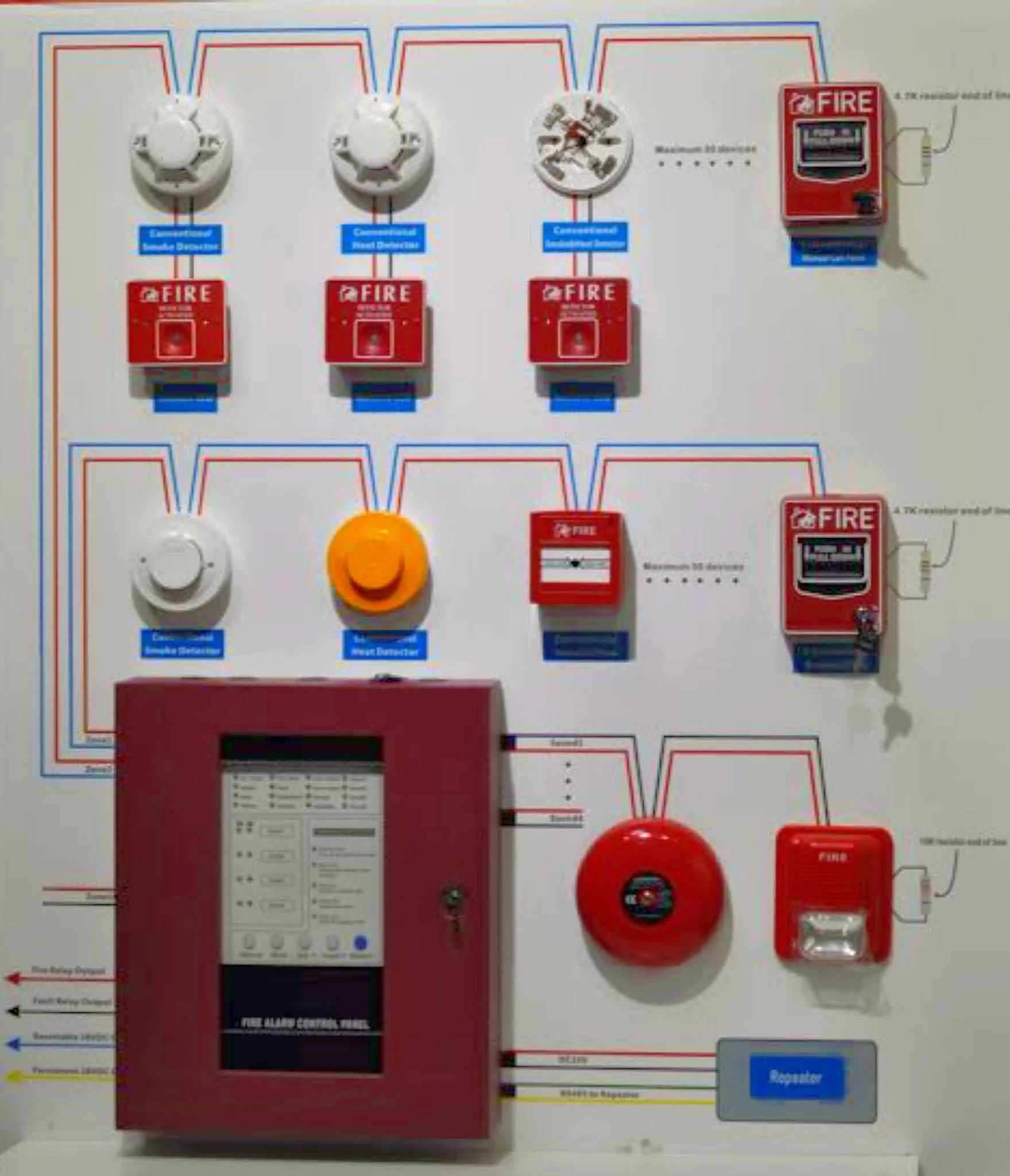
from the previous figure we find that :
- Break glass (also called manual pull stations) and detectors can be installed in the same Zone .
- Audible alarm devices (like Bells ,serines ,horns) and visible alarm devices (like strobes or flashers) are installed in an independent zone .
Disadvantages of Conventional fire alarm system
The conventional system can be considered non intelligent system for example if we have a conventional system installed in a building and suppose that a 30 detectors are installed in only one fire zone in different rooms inside the building .
If a fire occured in one of these rooms and the room's detector was activated , in this case the FACP panel will give alarm and indicate that there is a fire in the whole fire zone not the room the fire occurred in so the conventional system is used only inside small buildings
Maximum number of detectors per zone
Applications of conventional fire alarm system
Addressable fire alarm systems
In addressable systems , the detectors are wired in a closed loop as the fire alarm cable (consists of two wires (+,-)) exits from the FACP panel and connects all detectors in the same way as in conventional system but the cable returns again to the FACP panel .
 |
| Addressable fire alarm system |
 |
| Reliablity of conventional and addressable system |
Each detector or device (break glass , sounders and flashers) in the system is programmed to take a unique address so that in case of fire ,the address of activated detector will appear in the FACP screen and the location of fire will be detected accurately .
- Break glasses (manual pull stations) and detectors are connected in the same loop .
- Audible and visible alarm devices (serines,bells,horns,strobes..etc) are installed in an independent zone and an end of line resistor is installed at the end of zone .
- In some brands of addressable fire alarm systems, the Audible and visual alarm devices and detectors are wired in the same Loop .
Methods of programming Addressable fire alarm detectors


In this method , the detector is connected to a special electronic programming device which has a small screen and keyboard and the programmer can write the address using the keyboard and read the address through the small screen .
 |
| detector programming device |
3) Using DIP switches
DIP stands for Dual In-line Package
In this method DIP switches are fitted in the detector base as in the following fig :

Each switch has two positions (on , off) and there are 8 switches (1 through 8) all of them work in binary
As we said before the switch has two positions (on,off) , the position off means zero but the position on of the switch gives the values stated in the following table :

- The switch "1" is turned on and get 1
- The switch "2" is turned on and get 2
- The switch "6" is turned on and get 32
- The switch "7" is turned on and get 64
- All other switches are turned off
- The sum is 1+2+32+64=99 and this is the resulting address
- The following picure show the previous addressing process :

The detector is given an address by using two switches, the first switch represents ones and the other switch represents tens of the number or address required to be given to the detector .
The switch of ones has 10 positions (0 through 9) .
The switch of tens has either 10 positions (0 through 9) or 16 positions (0 through 15) .
Each switch of them has an indicator which can be turned to get the desired number .

For example, an addressable detector is needed to be given the address 37 , how ??the ones switch is set to number 7, and the tens switch is set to Number 3, so we get the address 37.
The detector then converts this digital number 37 to the binary number 100101 and sent it as a signal over the wires to the FACP panel .
In this method , the FACP panel gives addresses to all of the devices connected on the loops automatically depending on the physical position of each device on the loop.
Advantages of addressable fire alarm systems
- The addressable fire alarm system is more reliable the the conventional system because the addressable devices are connected in a loop and at both ends to the panel and if there is any break in the wires or loop or all the remaining devices will still connected .
- False fire alarms are reduced to minimum as even dust or contamination around the detector which can cause false alarms can be monitored by the detector itself.
- The cost if wiring up the addressable system is cheaper than the conventional system because in some addressable brands all the detectors, break glass ,serines, bells,horns and strobes can be connected in the same loop unlike the conventional system which uses an independent zone for audible and visible alarm devices .
- The addressable fire alarm panel can check and monitor all of the devices connected in the system so if any problem or issue occured to any detector this fault is discovered by the FACP panel which makes maintenance of the system much easier than than the conventional system.
Applications of addressable fire alarm systems
Can the addressable fire alarm panel be used instead of a conventional panel ?
Isolator module in addressable fire alarm systems
The isolator module is a module used in the addressable fire alarm system and is installed after each group of detectors in the single Loop (approximately every 20 : 25 detectors depending on the system brand)
 |
| Isolator module |
Function of isolator module

The following figure shows the wiring of the isolator module
 |
| Wiring of isolator module |
The isolator module may be used inside a single loop which connects all the detectors of all floors of a building and at each floor in the building , two isolator modules are installed at the beginning and end of the detectors of each floor
In any floor in the building , if a short circuit occured in the loop wires then the two isolator modules installed at the beginning and end of this floor will isolate all the detectors of this floor but the remaining detectors of other floors will still connected and operate through the two directions of loop .

Sometimes , detectors with isolator module base can be used instead of a separate isolator module and in this case ,only two detectors will be isolated from the loop instead of isolating 10 or more detectors if the separate isolator modules are used but the whole system cost will be more expensive.
 |
| detector with isolator base |
Remote LED indicators in fire alarm systems
 |
| Remote led indicator |
The remote led indicator is a device that contains a small LED lamp and is connected through two wires to the base of the detector to give an indication to the status of the detector which it is connected to as it will light whenever the detector gives alarm and activated.
Remote led indicator is used when the detector is located out of sight or it is difficult to see its status like in a ceiling void , behind a locked door , roof spaces, in lift shafts and escalator machine rooms then the indicator will then show the location of alarm .
Some versions of led indicators can be connected to more than one indicator located in the same room to show the status of any of these indicators whenever it gives alarm .
 |
| Wiring of remote led indicator |
fire alarm repeater panel
 |
| Repeater panel |
- When there is a need to install an addressable fire alarm system in a building which is far away from the main FACP panel existed in the main building so we use a repeater panel in this building as an extension to the main FACP panel and is connected or linked to it .
- If there is a main FACP panel that all its loops reached to the maximum number of detectors or alarm devices that can be connected to them and there is a need to add new fire alarm devices to the system so we can use a repeater panel and add the new devices to it and connect this repeater panel to the main FACP panel .
- When the main FACP reaches the maximum number of loops that can be connected to it so a repeater panel is used and any required new loops are connected to it .

The repeater is suitable for up to 8 zones and displays all the same functions as the main FACP panel , but with the addition of an indicator test facility .
There are two types of repeater panels :
Active repeater panel : it provides full information or indication of events at the main panel and also provides controls of fire system from the repeater panel
Passive repeater panel: it provides partial indication of events and no control .
The connection between main FACP panel and Repeater paned is achieved by using two cables ,the first cable is a power cable and the other cable is a data or communication cable (RS485 cable)
